Install Guide
- Taemin Shin
- Jun 15, 2025
- 3 min read

Updated: Jul 7, 2025
Welcome to the Guiarbox kit install guide. This post will take you through all the detailed steps of installing the kit in your guitar. For the best result, carefully read the entire post before starting.
This guide was made for guitars with pickguards, which helps cover up any imperfections that may occur during the installation process. Work at your own risk for guitars without a pickguard(e.g., Les Paul, PRS, certain superstrats)
Note: This guide assumes you know how to route and solder
*Since this is a DIY kit and all parts are thoroughly tested before shipping, we do not offer refunds. If you’re concerned about this, you may choose to source the individual parts yourself from sellers who do offer refunds.
Remove the neck for convenience.

Remove a screw and assemble the display ramp as shown below. Then mark the centers of the two other holes.

Drill through the pickguard and into the wood approximately 1.5 cm with the correctly sized bits.

Trace the outline of the pickguard. Remember to do it on the display side too.

Remove the pickguard

Align the main module against the side of the pickup cavity and mark the boundaries of each side.


Temporarily secure the pickguard in place using two screws and position the encoder so it doesn't protrude out of the pickguard or cross the lines for the main module. Mark the center.


Drill through the pickguard and slightly into the wood using an 8mm bit. 7 is better if you have one.

Before moving on, desolder the pickguard from the body. Take a picture so you know how to put it back together.
Start routing layer by layer, comparing the bit length with the height of the main module.


Don't knock out the pickup cavity wall until last. You should use it as a platform for the router body.
IMPORTANT!
Don't forget to route a way for the display wires(I did). Just connect the neck pickup cavity to the center hole. Leave the original screw hole intact. Refer to steps 15 and 18 if you are confused.


This is what it looks like when finished. I didn't bother making it neat, but you can if you want to.
Mark the outline of the battery holder and the four screw holes.


Route.


Drill.


Widen the ground wire hole or make a new one


Connect the battery cavity to wherever the other hole is
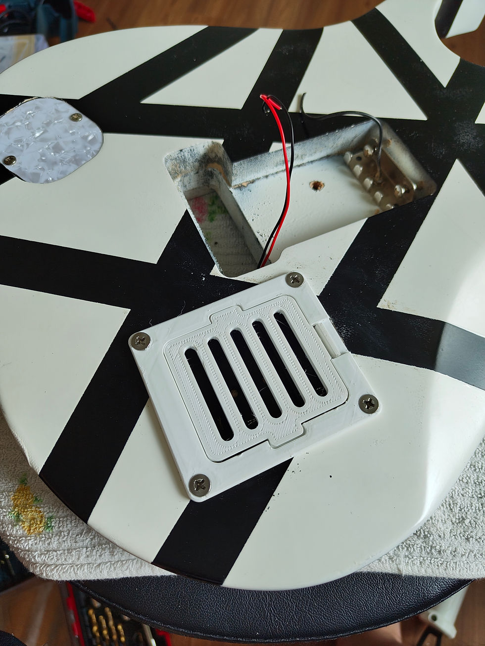
Install the battery holder and cover.


Install the main module.


Install the display ramp.
Use the included bolt and nut. When done, let the wires through the center hole.


Install the switch and the encoder(a photo is missing, sry)

Wire everything.
When connecting the female connectors to the header pins, push by the wire, not the connector. This ensures they are pushed all the way in. Try different orientations if they are still loose.
Display | Main Module |
+ | 3.3v |
- | GND |
CK | 13 |
SI | 11 |
CS | 4 |
RT | 9 |
DC | 5 |
Encoder | Main Module |
GND | GND |
Button | 1 |
Pin A | 2 |
Pin B | 3 |


Testing & finishing up

Before closing the pickguard, test all functions.
Power switch
Display
Rotary encoder left
Rotary encoder right
Rotary encoder button
Guitar sound when power is on
Guitar sound with effects when power is on
Other sounds (metronome, etc.)
Guitar sound when power is off
Original guitar circuit(tone, volume, pickup selector, etc.)
If everything works, hot glue the pins and the SD card extender in place. If not, go debug.


Now put the neck back on, restring, and enjoy!
If you have any questions, feel free to leave a comment, email, or DM @taeminshin27.
love it